Development Kit details
Inside the Qualcomm® Robotics RB1/RB2 Development Kit
The development kit includes a SOM (Qualcomm® QRB2210 for Qualcomm Robotics RB1 and Qualcomm® QRB4210 for Qualcomm Robotics RB2) mounted on a credit card sized mainboard that houses many peripheral interfaces and a robust expansion interface that supports the addition of multiple stackable mezzanine cards for added functionality.
Figure 1. Top and bottom view
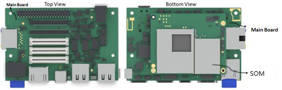
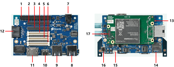
Figure 2. Qualcomm Robotics RB1/RB2 Mainboard connectors
| Label | Key Main Board Interfaces | Name | Details |
| 1 | Low speed connector | LS1 | Low speed interface: SPI, I2C, UART, 12V,5V,1V8, PWM, I2S(Optional), GPIO’s power same as 96Board specification |
| 2 | Low speed connector | LS2 | Low speed interface: I2S(Default), PM8008 LDOsx7, Flash LED, Pmic_1V8 (for UIM2), DMIC, speakers, CAN, GPIO’s power additional to 96Boards specification |
| 3 | Low speed connector | LS3 | Low speed interface: AMIC X 3, MIC_BIAS X3, headphone (reserved for QRB2210), PMIC_1V8 (for UIM1), SPI, I2C, I3C, GPIO’s, power, reference clocks, additional to 96Boards specification |
| 4 | High-speed connector | HS2 | CSI, USB SS, USB HS, camera MCLK additional to 96Boards specification |
| 5 | High-speed connector | HS3 | DSI CIK additional to 96Boards specification |
| 6 | High-speed connector | HS1 | SDIO, DSI, CSI, USB HS, I2C same as 96Boards specification |
| 7 | Power | DC power input | +12 V from wall supply |
| 8 | USB connector 1 | USB Type A (host mode) | USB 3.1 Gen 2 through USB hub |
| 9 | USB connector 2 | USB Type A (host mode) | USB 3.1 Gen 2 through USB hub |
| 10 | USB-C connector | USB Type-C | USB Type-C (debug) |
| 11 | HDMI | HDMI out connector | Up to 4K at 60 Hz with audio |
| 12 | Ethernet | Ethernet connector | RJ45 Ethernet through USB 3.0 (1 GB) |
| 13 | Antenna | Antenna connector 0 | 2.4/5 GHz printed antenna (on interposer) |
| 14 | microSD card | microSD card | microSD card tray |
| 15 | FAN connector | Wafer top entry connector | 4PIN, PH1.0 mm |
| 16 | Debug UART | Micro USB connector | Connector with FTDI USB to UART converter |
| 17 | JTAG board connector | JTAG | JTAG debug |
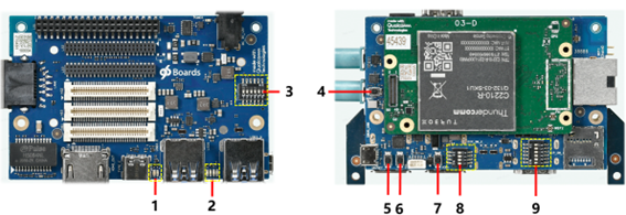
Figure 3. LEDs, buttons, and dip switches on Qualcomm Robotics RB1/RB2 main board
| Label | Key Main Board Interfaces | Name | Details |
| 1 | LEDs | Wi-Fi and Bluetooth LEDs | Yellow and blue, same as 96Board specification |
| 2 | LEDs | User LEDs | Green, same as 96Board specification |
| 3 | DIP_Switches (DIP_SW_3) | User controllable options | Six sub-switches |
| 4 | Push Button Switch - PWR | Power on button | Momentary switch |
| 5 | Push Button Switch – Vol - | Volume down button | Momentary switch |
| 6 | Push Button Switch – Vol + | Volume up button | Momentary switch |
| 7 | Push Button Switch – F_USBBOOT | Forced USB boot | Momentary switch |
| 8 | DIP_Switches (DIP_SW_2) | Boot config control | Four switches |
| 9 | DIP_Switches (DIP_SW_1) | User controllable options | Six switches |
Figure 4. Dip switches on Qualcomm Robotics RB1/RB2 mainboard
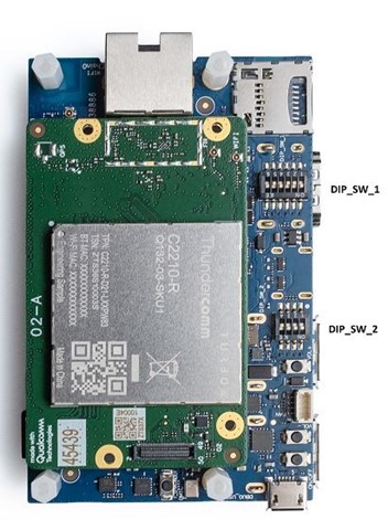
| DIP_SW_1 | Name | Details | Default |
| 1 | Mic switch | ON – Off board DMIC OFF – On board DMIC | OFF |
| 2 | 96Board Switch | ON – Compatible with 96Board OFF – LS1/HS1 same as DVT | OFF |
| 3 | SD_CARD | ON – Off board SD Card OFF – On board SD Card | OFF |
| 4 | HDMI switch | ON – DSI0 to HS1 connector OFF – DSI0 to HDMI bridge | OFF |
| 5 | CAN switch | ON – SPI (QUP5) to LS1 connector OFF – SPI (QUP5) to CAN controller | OFF |
| 6 | HUB_Debug_USB_SWITCH | ON – SOM_USB3.0 TO Type C OFF – SOM_USB3.0 TO USB_HUB | OFF |
| DIP_SW_2 | Name | Details | Default |
| 1 | BOOT_CONFIG_1 [GPIO_50] | Selects external boot devices (See table below) | OFF |
| 2 | BOOT_CONFIG_2 [GPIO_51] | OFF | |
| 3 | BOOT_CONFIG_3 [GPIO_53] | OFF | |
| 4 | BOOT_CONFIG_0 [GPIO_48] | ON – Disables WDOG OFF – Enables WDOG | OFF |
| DIP_SW_3 | Name | Details | Default |
| 1 | Board_HS2_USB_SWITCH | ON – HUB_USB3.0 to HS2 connect OFF – On board HUB_USB3.0 (Type A) | OFF |
| 2 | WSA_DMIC_SWITCH | ON – DMIC to LS2 Connect OFF – Speaker Protection | OFF |
| 3 | CBL_PWR_N | ON – Auto power-up OFF – PUSH power button to power up | OFF |
| 4 | I2S_Switch | ON – I2S to LS1 connector OFF – I2S to LT9611UCX | OFF |
| 5 | UART_SPI_Switch | ON – QUP0 to LS3_SPI OFF – QUP0 to LS1_4 Wire UART | OFF |
| 6 | Debug UART | ON – Off board Debug UART OFF – Onboard Debug UART | OFF |
The table here describes the GPIO / DIP_SWITCH_2 Configuration
| DIP setting | GPIO | Boot device | ||
| FAST_BOOT GPIO bit (2:0) | 53 | 51 | 50 | |
| 000(0X00) | 0 | 0 | 0 | Default: eMMC → uSD → USB (SS/FS/HS) |
| 001(0X01) | 0 | 0 | 1 | SDC2 → eMMC → USB(SS/FS/HS) |
| 010(0X02) | 0 | 1 | 0 | USB (SS/FS/HS) Boot only |
| 011(0X03) | 0 | 1 | 1 | Reserved |
| 100(0X04) | 1 | 0 | 0 | NAND → eDL |
| 101(0X05) | 1 | 0 | 1 | eMMC → USB(SS/FS/HS) |
| 110(0X06) | 1 | 1 | 0 | eMMC → uSD → eDL |
| 111(0X07) | 1 | 1 | 1 | Reserved |
| Other | Reserved | – | – | – |
RF Antennas on Qualcomm Robotics RB1/RB2
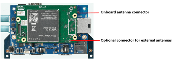
Qualcomm Robotics RB1 and Qualcomm Robotics RB2 use dual band (2.4/5 GHz WLAN/BT antennas) located on the main board.
- In Qualcomm Robotics RB1, Qualcomm® WCN3950 supports WLAN 1 × 1 802.11a/b/g/n/ac, Bluetooth 5.0, and FM (Bluetooth antenna can be dedicated or shared with the Wi-Fi antenna)
- In Qualcomm Robotics RB2, Qualcomm® WCN3988 supports WLAN 1 × 1 802.11a/b/g/n/ac, Bluetooth 5.1, and FM (Bluetooth antenna can be dedicated or shared with the Wi-Fi antenna)
- The QRB2210 and QRB4210 SOMs use a shared Bluetooth/Wi-Fi approach, on RF chain 0
- If the user needs to use the onboard antenna, an external coaxial cable is required to connect the SOM with the onboard antenna on the main board.
- If necessary, users also can plug in one external antenna on the SOM via industry standard MHF-4 coax connectors.
Qualcomm branded products are products of Qualcomm Technologies, Inc. and/or its subsidiaries.