Mezzanine Board Details
Navigation Mezzanine Board
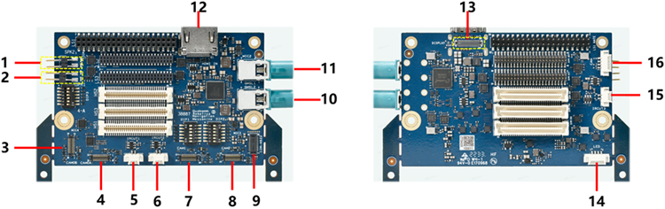
Components of the navigation Mezzanine board
| Label | Key MEZZ board interfaces | Name | Details |
| 1 | Speaker connector 2 | SPKR 2 | Not used |
| 2 | Speaker connector 1 | SPKR 1 | |
| 3 | Camera module connector | CAM0B | 1-lane OV9282 |
| 4 | Camera module connector | CAM0A | 4-lane or 2-lane OV9282 |
| 5 | IRCUT connector 1 | IRCUT 1 | IRCUT |
| 6 | IRCUT connector 2 | IRCUT 2 | IRCUT |
| 7 | Camera module connector 1 | CAM1 | 4-lane OS05A10(for RB1) or 4-lane OS08A10 (for RB2) Or TOF |
| 8 | Camera module connector 2 | CAM2 | Reserved |
| 9 | Sensor | Sensor | IIM_4622 (reserved) |
| 10 | GMSL connector 2 | GMSL 2 | GMSL2 camera inputs (using MAX9296A) |
| 11 | GMSL connector 1 | GMSL 1 | GMSL1 camera inputs (using MAX9296A) |
| 12 | HDMI in connector | HDMI IN | HDMI IN compliant with HDMI 2.0b, HDMI 1.4 and DVI1.0 |
| 13 | LCD panel connector | LCD | TFT LCD, 5.45-inch, 720 X RGB X 1440 dots |
| 14 | LED | LED | 2 GPIOs (reserved) |
| 15 | IRCUT connector 3 | IRCUT 3 | IRCUT |
| 16 | CAN connector | CAN | CAN interface |
Navigation mezzanine board supports the following key components -
Cameras
On Qualcomm® Robotics RB1 -
- Main camera (OS05A10), part number: HZ5F22, intended to be plugged into connector CAM1, CSI1
- Tracking camera (OV9282), part number: OV9282, intended to be plugged into connector CSI0
- Two CAM/CSI camera ports with identical pinouts, CSI0 is split into two cameras (CAM0A and CAM0B)
- CAM1 connector includes an option for a higher supply voltage of 5 V, this will accommodate Panasonic TOF camera.
On Qualcomm® Robotics RB2 -
- Main camera (OS08A10), part number: HZ8F27, intended to be plugged into connector CAM1, CSI1
- Tracking camera (OV9282), part number: OV9282, intended to be plugged into connector CSI0
- Three CAM/CSI camera ports with identical pinouts, CSI0 is split into one camera (CAM0A)
- CAM1 connector includes an option for a higher supply voltage of 5 V, this will accommodate Panasonic TOF camera.
Common camera features in Qualcomm Robotics RB1 and Qualcomm Robotics RB2 development Kits -
- 2x GMSL2 camera inputs (using MAX9296A), CSI0 & CSI1
- Support HDMI IN function: Compliant with HDMI2.0b, HDMI1.4 and DVI1.0, data rate up to 6Gbps
- Reserved IRCUT connector
Sensors:
Reserved IIM-4622 connector
Display:
DSI display (and touch), part number: UE055HD-AP40-A047D, TFT LCD,5.45 inch,720 X3 RGB X 1440 dots.
Audio:
- Four digital PDM mics that interface directly to Qualcomm® QRB2210, Qualcomm® QRB4210 chipsets
- Speaker connectors
Navigation Mezzanine DIP Switches
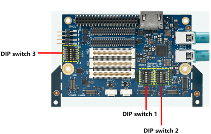
Navigation Mezzanine DIP Switch details
| DIP switch | Name | Details | Default |
| DIP switch 1 | |||
| 1 | I2S_SWITCH | ON – Pass through OFF – On board | OFF |
| 2 | GSML_EN_SWITCH | ON – Pass through OFF – On board | OFF |
| 3 | GPIO_1_SWITCH | ON – Pass through OFF – On board | OFF |
| 4 | SPI_SWITCH | ON – Pass through OFF – On board | OFF |
| 5 | I2C_Display_SWITCH | ON – Pass through OFF – On board | OFF |
| 6 | HDMI_IN_EN_SWITCH | ON – Pass through OFF – On board | OFF |
| DIP switch 2 | |||
| 1 | DIP_CSI0A_B_SWITCH | ON – Selects camera CAM0A OFF – Selects camera CAM0B | OFF |
| 2 | DISPLAY_SWITCH | ON – Pass through OFF – DSI0 TO LCD Interface | OFF |
| 3 | IIM_4622 SWITCH | ON – Pass through OFF – GPIO TO IIM_4622 | OFF |
| 4 | CSI0_SWITCH | ON – Pass through OFF – On board | OFF |
| 5 | CSI1_SWITCH | ON – Pass through OFF – On board | OFF |
| 6 | CSI2_SWITCH | ON – Pass through OFF – On board | OFF |
| DIP switch 3 | |||
| 1 | CAM0_GSMLA_SWITCH | ON – Selects camera CAM0A&B OFF – Selects GSMLA | OFF |
| 2 | DMIC_Switch | ON – Pass through OFF – On board | OFF |
| 3 | CAM1_GSMLB_SWITCH | ON – Selects GSMLB OFF – Selects CAM1 OR HDMI_IN | OFF |
| 4 | CAM1_HDMI_IN_SWITCH | ON – Selects CAM1 OFF – Selects HDMI_IN | OFF |
| 5 | CAM2_HDMI_IN_SWITCH | ON – Selects CAM2 OFF – Selects HDMI_IN | OFF |
| 6 | CSI1&CSI2_HDMI_IN_SWITCH | ON – Selects CSI1 OFF – Selects CSI2 | OFF |
TDK Mezzanine Board
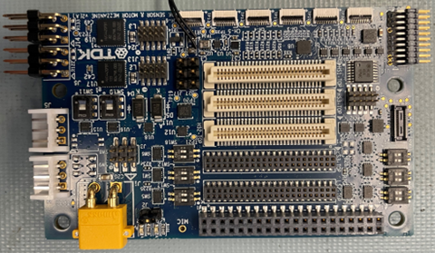
Components of the TDK Mezzanine Board
| Key component | Name |
| Magnetometer | AKM AK09940 |
| Single IMU | ICM-42688-P |
| Dual IMU | IIM-4622x (off board) |
| pressure sensor | TDK InvenSense ICP-10111 |
| Temp sensor and ADC | ADS7052 and B57861S0103A039 |
| Digital PDM mic (x1) | InvenSense T5818 |
| Chirp (x6 connectors) | CH-101/201 (off board) |
| motor driver (x2) | Micronas HVC4223 |
| Dynamixel motors | Two connectors |
TDK Mezzanine DIP Switch Details
| Name | Switch function and position (ON/OFF) |
| SW8 - 1 | ON - enable adjustable supply |
| SW8 - 2 | Not used |
| SW12 - 1 | ON - DMIC passthrough, OFF - onboard DMIC enabled |
| SW12 - 2 | ON - LS1 UART (QUP13) passthrough, OFF - LS1 UART to motors |
| SW14 - 1 | ON - LS1 SPI (QUP17) passthrough, OFF- SPI to temp sensor |
| SW14 - 2 | ON - LS3 SPI (SSC QUP2) passthrough, OFF - SPI to IMU |
| SW16 - 1 | ON - LS1 I2C0 (QUP4) passthrough, OFF - I2C to Chirp |
| SW16 - 2 | ON - LS1 I2C1 (QUP15) passthrough, OFF - I2C to Chirp |
| SW17 - 1 | ON - LS1 I2C (QUP1) passthrough, OFF - I2C to Chirp |
| SW17 - 2 | ON - LS3 I2C (SSC QUP4) passthrough, OFF - I2C to Chirp |
| SW18 - 1 | ON - HS2 I2C (QUP14) passthrough, OFF - I2C to Chirp |
| SW18 - 2 | ON - LS3 I2C (SSC QUP0) passthrough, OFF - I2C to Chirp |
| SW19 - 1 | ON - select single IMU, OFF - select 2nd IMU |
| SW19 - 2 | ON - connect dynamixel direction control |
| SW10 | ON - connect LS1 UART (QUP13) to HVC4223 master, OFF - connect to SW11 |
| SW11 | ON - connect dynamixel motors to HVC4223 slave controller, OFF - connect LS1 UART to Dynamixel motors |
| - | SW10 and SW11 both ON = LS1 UART connected to HVC4223 master and Dynamixels connected to HVC4223 slave SW10 and SW11 both OFF = LS1 UART connected to Dynamixels directly, HVC’s not connected |
Qualcomm branded products are products of Qualcomm Technologies, Inc. and/or its subsidiaries.