Main Board Details
How to Power ON the device
To power on the Qualcomm® Robotics RB1/RB2 development kits, +12 V needs to be applied to the barrel jack with the supplied wall power adapter. One can boot up the board by making one of the following choices-
- Auto power ON - The DIP_SW_3 PIN 3 is set to the ON position
- Manual Power ON - set DIP_SW_3 PIN 3 to OFF position and press PWR button for 2 seconds
- Power ON with USB plugged in – set DIP_SW_1 PIN 6 to ON, adb interface will only work if the dip switch is set to ON position
Boot up process can be observed by viewing the boot message logs by plugging in a micro-USB cable into the debug port on the side and using a serial terminal (such as PuTTY).
To reboot the device manually, hold down the PWR button for at least 20 seconds.
Note: The device will boot, and the green LED will flash only if the USB Type-C cable is plugged in and the main power is not plugged in.
Main Board Interfaces for Qualcomm Robotics RB1/RB2 Development Kits
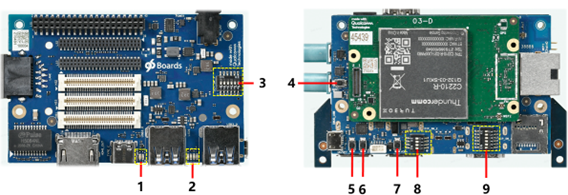
The following table describes the available buttons and status LEDs on the mainboard.
| Label | Key Main Board Interfaces | Name | Details |
| 1 | LEDs | Wi-Fi and Bluetooth LEDs | Yellow and blue, same as 96Board specification |
| 2 | LEDs | User LEDs | Green, same as 96Board specification |
| 3 | DIP_Switches (DIP_SW_3) | User controllable options | Six sub-switches |
| 4 | Push Button Switch - PWR | Power on button | Momentary switch |
| 5 | Push Button Switch – Vol - | Volume down button | Momentary switch |
| 6 | Push Button Switch – Vol + | Volume up button | Momentary switch |
| 7 | Push Button Switch – F_USBBOOT | Forced USB boot button | Momentary switch |
| 8 | DIP_Switches (DIP_SW_2) | Boot config control | Four switches |
| 9 | DIP_Switches (DIP_SW_1) | User controllable options | Six switches |
The table here describes the DIP Switches
| DIP_SW_1 | Name | Details | Default |
| 1 | Mic switch | ON – Off board DMIC OFF – On board DMIC | OFF |
| 2 | 96Board Switch | ON – Compatible with 96Board OFF – LS1/HS1 same as DVT | OFF |
| 3 | SD_CARD | ON – Off board SD Card OFF – On board SD Card | OFF |
| 4 | HDMI switch | ON – DSI0 to HS1 connector OFF – DSI0 to HDMI bridge | OFF |
| 5 | CAN switch | ON – SPI (QUP5) to LS1 connector OFF – SPI (QUP5) to CAN controller | OFF |
| 6 | HUB_Debug_USB_SWITCH | ON – SOM_USB3.0 TO Type C OFF – SOM_USB3.0 TO USB_HUB | OFF |
| DIP_SW_2 | Name | Details | Default |
| 1 | BOOT_CONFIG_1 [GPIO_50] | Selects external boot devices (See table below) | OFF |
| 2 | BOOT_CONFIG_2 [GPIO_51] | OFF | |
| 3 | BOOT_CONFIG_3 [GPIO_53] | OFF | |
| 4 | BOOT_CONFIG_0 [GPIO_48] | ON – Disables WDOG OFF – Enables WDOG | OFF |
| DIP_SW_3 | Name | Details | Default |
| 1 | Board_HS2_USB_SWITCH | ON – HUB_USB3.0 to HS2 connect OFF – On board HUB_USB3.0 (Type A) | OFF |
| 2 | WSA_DMIC_SWITCH | ON – DMIC to LS2 Connect OFF – Speaker Protection | OFF |
| 3 | CBL_PWR_N | ON – Auto power-up OFF – PUSH power button to power up | OFF |
| 4 | I2S_Switch | ON – I2S to LS1 connector OFF – I2S to LT9611UCX | OFF |
| 5 | UART_SPI_Switch | ON – QUP0 to LS3_SPI OFF – QUP0 to LS1_4 Wire UART | OFF |
| 6 | Debug UART | ON – Off board Debug UART OFF – Onboard Debug UART | OFF |
The table here describes the DIP_SWITCH_2 Configuration
| GPIO | Boot device | |||
| FAST_BOOT GPIO bit (2:0) | 53 | 51 | 50 | |
| 000(0X00) | 0 | 0 | 0 | Default: eMMC → uSD → USB (SS/FS/HS) |
| 001(0X01) | 0 | 0 | 1 | SDC2 → eMMC → USB(SS/FS/HS) |
| 010(0X02) | 0 | 1 | 0 | USB (SS/FS/HS) Boot only |
| 011(0X03) | 0 | 1 | 1 | Reserved |
| 100(0X04) | 1 | 0 | 0 | NAND → eDL |
| 101(0X05) | 1 | 0 | 1 | eMMC → USB(SS/FS/HS) |
| 110(0X06) | 1 | 1 | 0 | eMMC → uSD → eDL |
| 111(0X07) | 1 | 1 | 1 | Reserved |
| Other | Reserved | – | – | – |
Qualcomm branded products are products of Qualcomm Technologies, Inc. and/or its subsidiaries.