Hi Qualcomm Team:
i use Interrupt and timer output PIN.
i use LA(logic analyzer) look output data, There is a problem with timer.
i set 100 microseconds output GPIO (PIN 55) toggle.
this my timer set
static qapi_TIMER_handle_t test_timer_100us_handle;union{qapi_TIMER_define_attr_t Def;qapi_TIMER_set_attr_t Set;} test_timer_100us;qapi_Timer_Undef( test_timer_100us_handle);/* Define the timer. */memset(&(test_timer_100us.Def), 0, sizeof(test_timer_100us.Def));test_timer_100us.Def.deferrable = false;test_timer_100us.Def.cb_type = QAPI_TIMER_FUNC1_CB_TYPE;test_timer_100us.Def.sigs_func_ptr = timer_func;test_timer_100us.Def.sigs_mask_data = 0;qapi_Timer_Def(&test_timer_100us_handle, &(test_timer_100us.Def));test_timer_100us.Set.time = time;test_timer_100us.Set.reload = true;test_timer_100us.Set.max_deferrable_timeout = time;test_timer_100us.Set.unit = QAPI_TIMER_UNIT_USEC;qapi_Timer_Set(test_timer_100us_handle, &test_timer_100us.Set);static void timer_func(void* data){static uint8_t test_timer_us = 0;if((test_timer_us%2) == 1){api_TLMM_Drive_Gpio(Four_In_One_Module_Gpio_id, 55, QAPI_GPIO_LOW_VALUE_E) ;}else{qapi_TLMM_Drive_Gpio(Four_In_One_Module_Gpio_id, 55, QAPI_GPIO_HIGH_VALUE_E) ;}if(test_timer_us == 10){test_timer_us = 0;qapi_Timer_Stop(test_timer_100us_handle);}test_timer_us++;}
my LA Capture data
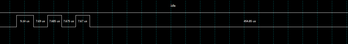
i use interrupt is GPIO 58, Trigger interrupt will generate a set test_timer_100us_handle.
qapi_GPIOINT_Register_Interrupt(interrupt_hdl, 58, (qapi_GPIOINT_CB_t)KeypadCardInt_Step1,0, QAPI_GPIOINT_TRIGGER_LEVEL_LOW_E, QAPI_GPIOINT_TRIGGER_LEVEL_HIGH_E, false) ;qapi_GPIOINT_Enable_Interrupt(interrupt_hdl,58);
This question may be caused by any incident?
Best Regards,
Rick
Hi Rick,
I'm not sure but have you ever reviewed PWM driver which can generate digital signals based on the configuration like frequency, duty cycle, and phase.
As per your digital signal pattern like 100us (high), 100us (low), 100us (high), 100us (low), ....,
we can say the frequency of signal is about 5000hz and duty cycle 50%.
Can you try to generate digital signal via PWM with following commands?
We can probe GPIO 13 on J5-19 pin on CDB20 board.
@Generate digital signal via PWM
Peripherals\PWM> output 500000 5000 0 7
where
frequency 500000 (= 5000hz * 100)
duty 5000 (= 50% * 100)
phase shift (= 0)
pwm channel 7 (GPIO 13, J5-19 pin)
Thanks
BR,
Jayden
Hi jaydenk:
you say use PWM, but it is output , i need input sample Continuous signal is 100us (microsecond).\
how can i do it?
Best Regards,
Rick
Hi Rick,
I can't figure out what are you looking for.
In your code, it looks like following for me
- to make digital output through GPIO (PIN 55) toggle.
- to make interrupt input source through GPIO (PIN 58) toggle.
Did you connect GPIO 55 to GPIO 58?
As per your snapshot, your output signal had a problem. I suggested to use PWM for the output signal.
Please describe what's problem in your setup.
Thanks
BR,
Jayden
Hi jaydenk
Best Regards,
Rick
Hi Rick,
Unfortunately, there is no special hardware support for capturing input signals on QCA402x.
There is also on HW timer on this chip.
May be this can be performed through GPIO interrupts if really want to do.
Once GPIO interrupt is hit on line change, read the status of the line.
Interrupt will be hit every 100us which may be concern to other tasks and also, not sure on impact on timing latency though if high priority interrupt is ongoing and it holds up 100us of CPU time.
Thanks
BR,
Jayden