HDR displays have been around for a long time in the PC and TV space. On the mobile side, OLED screens that have appeared in 2018 are starting to support a higher dynamic range and wider color gamut. To make better use of the screen’s wide color gamut and high dynamic range, Qualcomm launched True HDR gaming.
True HDR gaming is part of Snapdragon Elite Gaming, which was announced at the 2018 Snapdragon Tech Summit in Hawaii. This solution retains details and color to achieve the best user gaming experience. This is the first end-to-end HDR solution on mobile. True HDR gaming also fully takes advantage of Qualcomm Snapdragon platform GPU and DPU’s capability. Game Engine/GPU output the HDR content (RGBA1010102 format/BT2020 gamut) directly. Color Volume Mapping is performed by the Display Process Unit (DPU).
This guide is meant as an introduction and overview of the concepts related to HDR and present the Qualcomm True HDR gaming solution.
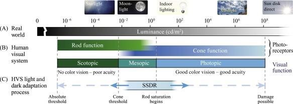
In the following image, the world’s luminance level is [0, infinite) candela per square meter(cd/m 2). Through adaption of rod and cone, the luminance human could perceive is around [10 −6, 10 8] cd/m 2.
Real-world luminance levels and the high-level functionality of the Human Visual system, image taken from [1]_ Perceptual Design for High Dynamic Range Systems.
By comparing the supported luminance, the displayed devices could be classified as Standard Dynamic Range (SDR) and High Dynamic Range (HDR).
SDR support luminance in [0.0002, 100] cd/m 2
HDR support luminance in [0.00005,1000 or larger] cd/m 2
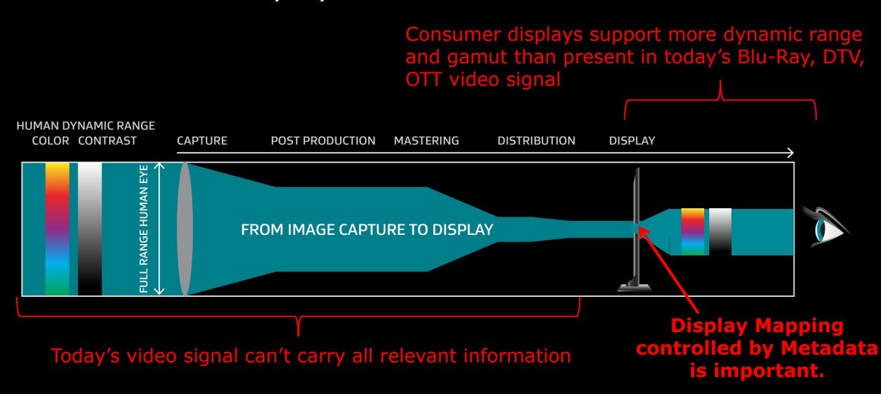
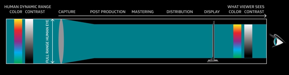
The figures below show the change of dynamic range and color gamut in the SDR and HDR pipeline.
Content delivery in SDR. Image Credit: Dolby Laboratories, Inc.
Content delivery in HDR. Image Credit: Dolby Laboratories, Inc.
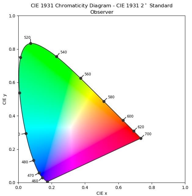
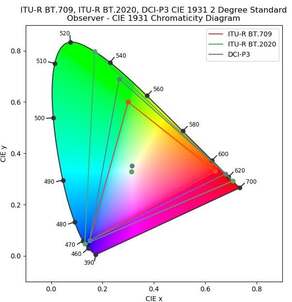
The human eye has three types of color sensors that respond to different ranges of wavelengths. The color consists of two parts: brightness and chromaticity. For example, the white and grey have same chromaticity and different brightness.
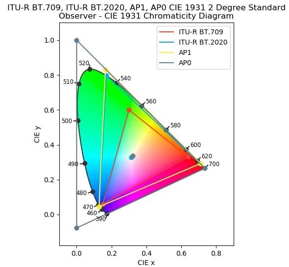
The International Commission on Illumination (CIE) created the CIE 1931 RGB color space. The horseshoe-shaped region represents what human could see in response to different light wavelength.
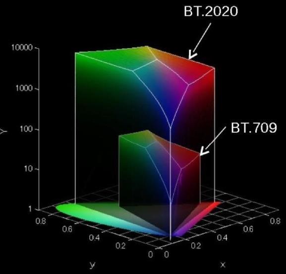
The color gamut is a specific, complete subset of colors. It is often referred to as the entire range of colors available on a display device. The following image shows various standards’ color gamuts.
Color volume mapping is the process of mapping content that was created on a mastering display down to a playback display. It includes tone mapping for Luminance and gamut mapping for Chromaticity.
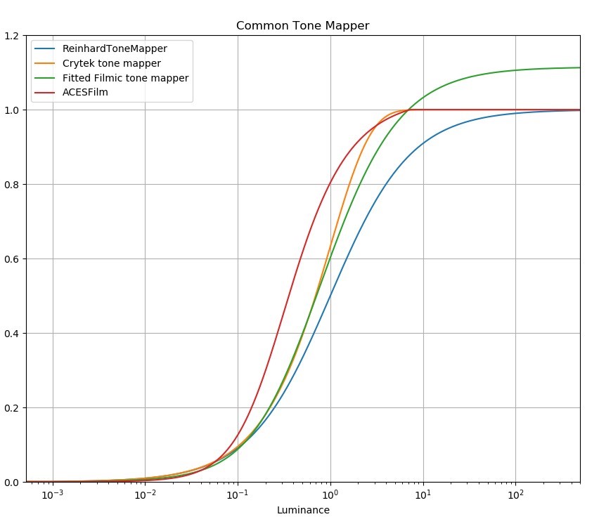
Tone mapping: The peak luminance of a playback HDR display will often be lower than the peak luminance of the reference display that is used to master HDR content. So tone mapping is necessary to convert the high luminance HDR content to suitable dynamic range that is supported by the playback display.
Gamut mapping: The primary colors of a playback HDR display are often less saturated than the reference HDR display. The wider content gamut must be mapped to the corresponding gamut of the playback display.
Note
When applying color volume mapping, the luminance and chromaticity attributes of both the reference display and the content must be passed to the display. These attributes are represented by the static metadata fields that are defined in the SMPTE ST 2086 standard.
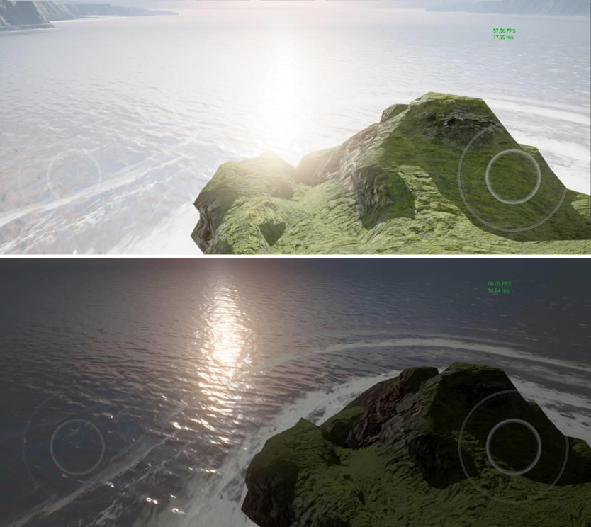
A True HDR image has a higher contrast. More details are preserved in highlights and shadowed areas. Qualcomm True HDR gaming is compatible with the HDR10 standard. In fact, the display process unit (DPU) expects HDR10 data input.
HDR Game content is produced on a reference display with a higher dynamic range and a wider gamut. The rendered scene is mapped to the dynamic range and color space supported by True HDR in the postprocessing phase, and the display is notified by metadata.
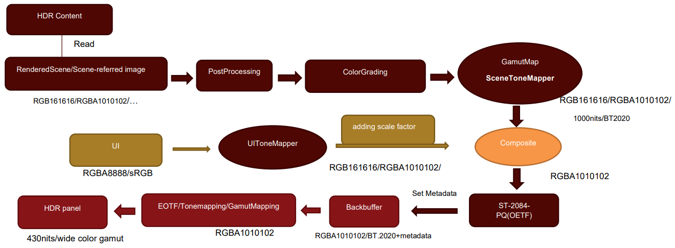
The following provides a detailed overview of the True HDR pipeline and how it functions:
HDR Content: Game content produced on a reference display with large color volume (higher dynamic range and wider color gamut).
Scene-referred image: Takes HDR content as input, adapts a realistic rendering approach such as physically based rendering (PBR) to generate a good HDR scene reference image with properexposure, rich highlights, and shadows.
Postprocessing, ColorGrading: Same as traditional game HDR.
GamutMap and Tonemapper: Maps the dynamic range and color space of the RenderedScene to the dynamic range and color space supported by True HDR.
UIToneMapper: Maps UI render data to HDR.
Adding a scale factor: Adds a scale factor to the UI to match with the main rendered scene.
Composite: Blends the scene HDR and UI HDR inputs. If the game relies on a lot of transparent UI, it would be easier to render the entire UI in a render target, and then blend with back-buffer, compared with direct render UI to back-buffer.
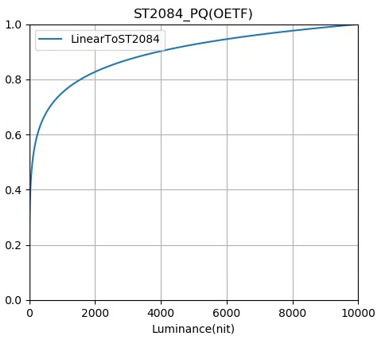
ST-2084-PQ(OETF): Data that True HDR requires the backbuffer to receive is ST-2084-PQEncoded. Therefore, the backbuffer would be encoded by ST-2084-PQ, and the encoded value is mapped to the range of [0.0,1.0].
EOTF/Tonemapping/GamutMapping: Handled by Qualcomm DPU.
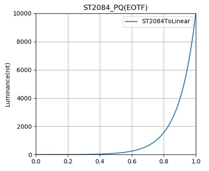
ST-2084-PQ(EOTF): Inverse of ST-2084-PQ(OETF).
Tonemapping: Maps output of EOTF to the actual color space used by the screen and the actual dynamic range.
GamutMaping: Maps one color space to another. The usual method is linear stretch or compression. The color space required by HDR10 standard is BT2020, but the actual screen cannot meet this requirement. The Qualcomm DPU will perform the color gamut conversion.
Even with HDR screens, the dynamic range of support is limited. Scene-referred images can generate very high dynamic range images. SceneToneMapper would map the input HDR scene (up to 10000 nit) to True HDR scene (1000 nit). UIToneMapper would map the UI data to True HDR data.
The Academy Color Encoding System (ACES) is often used in games.
For games, images after scene rendering are a Scene-Referred image. In the ACES pipeline, there are only three components:
Color grading: Grading in ACES Color Space.
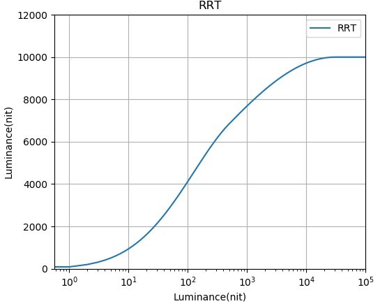
Reference Rendering Transform (RRT): Converts the scene-referred colorimetry to the display-referred. The color space is converted to the ACES defined AP0 color space. Dynamic range is converted to 0-10000 nits, so it allows for rendering to any output device.
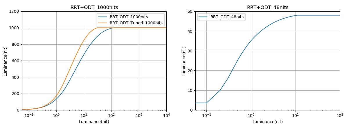
Output Device Transform (ODT): Converts the color space into the ACES defined AP1 color space. Dynamic range is mapped to the dynamic range supported by the device. Converts AP1 to the color space supported by the device before output. There are many ODTs, such as ODT_48nits, ODT_1000nits, ODT_2000nits, etc.
RRT+ODT_1000 nits (left) and RRT+ODT_48 nits (right)
To enable True HDR in OpenGL ES, the following extensions must be supported:
EGL_EXT_gl_colorspace_display_p3
EGL_EXT_gl_colorspace_bt2020_pq
EGL_EXT_surface_SMPTE2086_metadata
Note
Vulkan Swapchain/WSI for Android only supports VK_COLOR_SPACE_DISPLAY_P3_NONLINEAR_EXT. For additional information on how to enable this for Vulkan, check out the Enhancing graphics with wide color content guide from the Android Developers Documentation.