General
Use Variable Rate Shading
Variable Rate Shading (VRS) allows a fragment shader to color one or more pixels at a time, such that a fragment can represent one pixel or a group of pixels. Think of VRS as solving the inverse of what anti-aliasing techniques resolve. Anti-aliasing techniques sample each pixel more frequently to avoid aliasing and jagged edges by smoothing content with high variation. However, if surfaces to be rendered do not have a high color variation or will be blurred on a subsequent pass (e.g., with motion blur), performing shading operations on a 1:1 basis (one shading operation per one pixel) can be inefficient.
VRS allows developers to specify shading rates where only one shader computation is performed for a fragment and the result operation is applied to the specified pixel group configuration. When used properly, this should result in no visual quality degradation while significantly alleviating the GPU’s work to render a frame, thus conserving power and improving performance. With several high display rate mobile devices commercially available, like those powered by our Qualcomm® Snapdragon™ mobile platforms and their embedded Qualcomm® Adreno™ GPU’s, the need for shading every pixel for all surfaces being rendered is diminished.
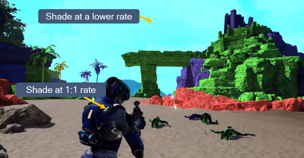
The following screenshot from our Variable Rate Shading demo shows how higher rate (per-pixel) shading should be used on highly detailed areas, while lower rates (shading fragments comprising groups of pixels) can be done on lower detail areas.
How Does Variable Rate Shading Work?
When the GPU renders and rasterizes objects into a surface, it does so at a rate of one sample per pixel (assuming multisampling is not used, although this concept can be applied to multisampling as well). Through graphics API extensions, a developer can modify the shading rate of a given surface to be coarser than a pixel, as shown in the following picture:
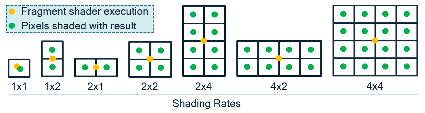
VRS in OpenGLES is exposed through the QCOM_shading_rate extension and the VK_KHR_fragment_shading_rate extension for Vulkan. The OpenGL ES extension includes a number of enumerations (e.g., GL_SHADING_RATE_1X1_PIXELS_QCOM, GL_SHADING_RATE_1X2_PIXELS_QCOM, etc.) for controlling the different fragment sizes. You can see a demonstration of the extension’s usage on our new Adreno GPU OpenGLES Code Sample Framework in GitHub.
The Vulkan, VK_KHR_fragment_shading_rate takes in a VkExtent2D struct in which developers specify the width and height of the desired fragment size.
Note
Support for VK_KHR_fragment_shading_rate on Snapdragon mobile platforms is coming soon.
Effective Ways to Modify Shading Rate These extensions can improve performance on heavy fragment-bound draw calls such as:
Surfaces where the color variance is low.
Surface areas that do not require per-pixel shading accuracy, such as color targets that will be downscaled through motion blur and areas that have significant changes in velocity field. If depth of field is used, there will be areas outside of the focus point that will be blurred.
Effects like motion volumetric rendering where a portion of the scene is processed at full shading rate and a portion can be processed at a reduced shading rate.
Note
Reducing shading rate can impact the visual quality of a rendered object if used inappropriately. On mobile devices where performance and power are tightly coupled, the use of courser shading rates can also improve power consumption and reduce the thermal profile of your game, ultimately increasing the user’s play time.
Occlusion Query usage
No more than 512 should be active, with usually a 3 frame delay for results. The performance of queries is coupled with the number of bins, the higher the bin count (from resolution, MSAA etc..) the more expensive the queries will be.
The recommended usage of Occlusion queries in Adreno GPU’s is to run them in direct mode whenever possible. One way to ensure this occurs is to issue all of the queries for a frame in one batch after a flush, E.g. Render Opaque -> Render Translucent -> Flush -> Render Queries -> Switch FBO. The driver has a heuristic which will understand that only queries have been issued to the surface and switch into direct.
Note
The overhead of queries will show up as an higher “% CP Busy” metric in Snapdragon Profiler.
In some test cases when issuing a lot of queries to a binned surface the CP overhead might jump to 20-40%, and drop to 4-6% in direct.
Bandwidth optimization
OpenGL ES applications can suffer from the bottleneck of being memory-bandwidth limited. This is a manifestation of the physical limitation of how much data the GPU can access within a given timeframe. The rate is not constant and varies according to many factors, including but not limited to:
Location of the data – Is it stored in RAM, VRAM, or one of the GPU caches?
Type of access – Is it a read or a write operation? Is it atomic? Does it have to be coherent?
Viability of caching the data – Can the hardware cache the data for subsequent operations that the GPU will be carrying out, and would it make sense to do this?
Cache misses can cause applications to become bandwidth-limited, which causes significant performance drops. These cache misses are often caused when applications draw or generate many primitives, or when shaders need to access many locations within textures.
There are two measures to take to minimize the problem of cache misses:
Improve the transfer speed rate – Ensure that client-side vertex data buffers are used for as few draw calls as possible; ideally, an application should never use them.
Reduce the amount of data the GPU needs to access to perform the dispatch or draw call that is hitting this constraint.
OpenGL ES provides several methods that developers can use to reduce the bandwidth needed to transfer specific types of data.
The first method is compressed texture internal formats, which sacrifice texture quality for the benefit of reduced mipmap size. Many of the compressed texture formats supported by OpenGL ES divide the input image into 4x4 blocks and perform the compression process separately for each block, rather than operating on the image as a whole. While it can seem to be inefficient from the point of view of data compression theory, it does have the advantage of each block being aligned on a 4-pixel boundary. This allows the GPU to retrieve more data with a single fetch instruction, because each compressed texture block holds 16 pixels instead of a single pixel, as in the case with an uncompressed texture. Also, the number of texture fetches can be reduced, provided that the shader does not need to sample texels that are too far apart.
The second method is to use packed vertex data formats. These formats are based on the premise that many vertex data sets will not suffer greatly from a reduction in the precision of their components. It is strongly recommended to use packed vertex data formats wherever possible.
For certain assets whose range span is known in advance, try to map the data onto one of the supported, packed vertex data formats. Taking normal data as an example, it is possible to map XYZ components onto the GL_UNSIGNED_INT_2_10_10_10_REV format by normalizing the 10-bit unsigned integer data range of <0, 1024> onto the floating-point range <-1, 1>.
The third method is to always use indexed draw calls. Always use an index type that is as small as possible while still being able to address all the vertices for the mesh being drawn. This reduces the amount of index data that the GPU needs to access for each draw call, at the expense of slightly more complicated application logic.
Depth range optimization
A common artifact in games is z-fighting, where two or more primitives have similar values in the depth buffer. The artifact becomes apparent when the camera view changes slightly and fragments from different primitives fight to win the depth test and become visible. There are several ways to eliminate z-fighting:
Modify the scene geometry to provide more distance between near planar surfaces (preferred).
Choose an EGL configuration with a larger depth buffer, e.g., 24 bits vs 16 bits, though performance may be impacted by using a larger buffer.
Tighten camera depth range (near and far clipping planes) allowing for more precision in the z direction, though this will not help coplanar primitives; consider rendering the scene with multiple ranges, one for near objects and one for far objects.
Other optimizations
The 3D rendering process is a compute-intensive activity. Screen resolutions are growing larger, with some about to reach Ultra HD resolution. This means that GPUs need to rasterize more fragments within the same fixed time period. Assuming a target frame rate of 30 fps, a game must not spend more than 33 ms on a single frame. If it does, then the number of screen updates per second will drop, and it will become more difficult for users to immerse themselves fully into the game.
Also, the busier the hardware is, the more heat it will generate. If, over an extended period of time, the GPU is not left with any idle time between frames, the device may become hot and uncomfortable to hold. If the temperature exceeds a certain safety threshold, the device may even automatically reduce the GPU clock frequency to prevent it from overheating. This will further degrade the user experience.
To reduce the load on the rendering hardware, an application can reduce the size of the render target used, e.g., if the native screen resolution is 1080p (1920x1080), it could be rendered to a 720p (1280x720) render target instead. Since the aspect ratio of the two resolutions is identical, the proportions of the image will not be affected. The reduced-size render target will not completely fill the screen, but OpenGL ES provides a fix for this issue.
OpenGL ES 3.0 introduced support for frame buffer blit operations. The contents of a draw buffer can be blit from one frame buffer to another. As part of the blit operation, the API also supports upscaling, which can be used to copy the contents of a texture of a smaller resolution to another texture of a larger resolution. Use upscaling to scale up the reduced-size render target to match the full native display size. The best strategy depends on how intensive the computations are that the GPU must perform for an application. The upscaling can be done either at the end of the rendering process or at some point in the rendering pipeline; e.g., one approach might be to render the geometry at 1:1 resolution, but apply postprocessing effects using render targets of a slightly lower resolution.
Note
Upscaling using a frame buffer blit is faster than the alternative approach of rendering a full screen quad directly to the back buffer, taking the reduced-size render target as a texture input.
Alternatively, control scaling through the Android API:
For applications written in Java, configure the fixed-size property of the GLSurfaceView instance (available since API level 1). Set the property using the setFixedSize function, which takes two arguments defining the resolution of the final render target.
For applications written in native code, define the resolution of the final render target using the function NativeWindow_setBuffersGeometry, which is a part of the NativeActivity class, introduced in Android 2.3 (API level 9).
At every swap operation, the operating system takes the contents of the final render target and scales it up so that it matches the native resolution of the display.
This technique has been used successfully in console games, many of which make heavy demands on the GPU and, if rendering were done at full HD resolution, could be affected by the hardware constraints discussed.